Services for the Oil and Gas Industry
Services for the Oil and Gas Industry
Upstream
- Monitoring and Control for applications such as core sample analysis
- Physical simulation of reservoirs
Production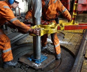
- Turnkey high-pressure test systems for safety valves.
- Manufacturing and quality control applications
- Controlling drilling operations
- Monitoring rheology data
Downstream
- Monitoring and control of pipelines, lab reactors, oil quality and viscosity, among others
High Pressure Test Systems for Oil and Gas
Optimation’s Test Systems teams working with the oil and gas industry have years of experience in successfully addressing and solving a wide variety of challenges facing test labs, production facilities, research and development work, and site installation/startup projects at client’s site. Specialized equipment, trained and skilled trades people, mechanical, process, automation and integration engineering services and a diverse project history allow us to rapidly put our experience to your benefit.
Example Pressure Test Systems
- Equipment Pod Test system
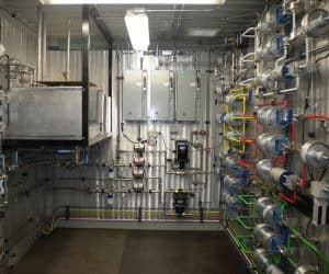
- Cell Room Equipment Test Panels
- Mobile Pressure Test Carts & Skids
- Test System-Tool Interface systems including software/hardware interface, recipe-controlled pressure test process, data acquisition, control charting, and formal report generation for clients.
- Blast Door Fabrications: L-shaped, Personnel, Long Horizontal, Sliding, Hinged, and other designs to fit client existing or new facility
- Equipment Safety Modifications, Process Monitoring and Alarms, and Emergency Shutdown systems
Where do you need us to start in your project’s life cycle?
Strategic Development and Requirements
- Business Case development
- Strategic User Requirements, System Functionality, Process Integration & Safety
- Strategic Cost & Schedule Estimates
- Process Concept Design
- Technology Selection
- Block Flow Diagram
- Site Equipment Concept Layout Drawings
- Control System Architecture
Preliminary Engineering
- Process Flow Diagram
- Final Customer/User Requirements Document
- Equipment General Arrangement Drawings
- Software Functional Specifications
- Long Lead Equipment Purchase Requisitions
- Preliminary Equipment List
- Bottoms-up Cost & Schedule Estimate
Final Design
- Detailed Process Mechanical, Machine Design, Electrical and Control Systems Design
- Piping & Instrumentation Drawings
- Detailed Mechanical and Electrical Fabrication and Installation Drawings
- Detailed Cost & Schedule Estimates
- Material Purchase Orders
- Process Equipment Specifications
- Equipment Operational and Software Functionality
- Execution Packages for Site Installation Bid Packages
- Final Equipment List
Project Execution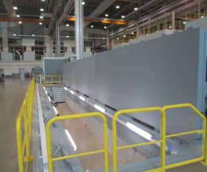
- Equipment Fabrication & Assembly
- Mechanical & Electrical Installation on site
- Fabrication Check Out, Debug, and Client FAT at Shop
- Installation Check Out, Debug, and Client SAT at Site
- Project Turnover with Safety, Operation, and Maintenance Training
- Equipment and Software Ongoing Support after Site Startup and Turnover
- As-Built drawings, Maintenance Documentation and Procedures, and Spare Parts Recommendations.
Control System/Data Acquisition
Real-time controller chassis for all operations, including valve control, data acquisition, and safety interlocks. Controller access through software running on a standard PC with a networked connection to the controller chassis. Flexible operator PC location – may be located as close as the test cell outer wall, or in a control room elsewhere in the test facility.
User interface screens show the system as a live P&ID and contain a mouse ‘point-and-click’ method of changing valve positions, and slider controls or numeric entry to set pump output.
We can provide systems with 3 levels of operator control:
Manual
- Valve on/off control
- Direct pump and metering valve output
Semi-automatic
- Pressure setpoint operation of pumps
- Bleed down to a setpoint at a given rate. (Or bleed down to a setpoint by following a predefined table of rates appropriate for given pressure ranges.)
Fully automatic
- Control systems for pressure up/hold/bleed down, or heat-up/cool down process steps. Fully automatic systems are by far the most chosen design, with clients having their own specific recipes for us to integrate into the new control system.
- In many cases the recipe execution exceeds the timing and precision of human operators.
- We can also provide an automation table for the recipe, which is a pressure-up or bleed-down table, where the operator can input the various set points prior to running the process and does not need to continually input set points during the process.
Graphing and charts, with output to a formal test report if needed for process documentation, or to send to outside clients for contract perforating work.
The control system can monitor and control all aspects of the perforation process, communicate with site services, connect to and activate existing building alarm systems, and upload test results to company IT systems if needed.
Data can be logged to network drives or corporate databases.
The control system can provide interlock functionality to inhibit pump or heater function beyond a predefined pressure or temperature setpoint when safety doors are not secured.